 |
|
AirWhere - Diagnostics
As there are quite a few components being used and anyone of these could potentially be faulty, alternatively there could be a fault in your wiring, these are the steps to follow to make sure everyting works ok. Hopefully now you have a flashed Node board and you can see the configuration webpage on the board.
Please update your AirWhere to the latest version before starting testing.
Alternative to Putty if your having problems getting that working is the Ublox GPS center software here :- Ublox Center - you can see your GPS lines on this aswell.
Part One - Checking GPS
1. Purchase an FTDI adapter - you can use your kobo to debug the various components, but an FTDI adapter makes things a lot easier and they are only £3 - FTDI. We have added a config change now so if you switch the AirWhere to be in OTG mode ( on the config page ) the AirWhere unit will send data up the USB port - so plug it in and then the com port that appears, use this for putty and all the data will appear.
2. Install your FTDI adapter, it will probably use the same drivers you have already installed for the board - check with device manager on your pc for the comport it has been assigned. This little device will read serial input from each the GPS and the board enabling you to debug any problems.
3. Now download Putty, which is a application which you can use to see the output from the board :- Putty
4.Load Putty and add in your details for your ftdi adapter you saw in the device manager, mine would be COM21, and then we are going to check your GPS is working first, the majority of them are 9600, so put this in as speed, then select serial and then open, a bluefly is 57600 and I have seen GPS units arrive with 38400..... if you have no manual with your GPS, try 9600 first and then 57600 and then 38400.
5.Now connect up your GPS to the FTDI board - 3v to VCC, GND - GND and then TX on the GPS to RX on the FTDI board, usually there is a light on the GPS that will illuminate to show you its on.
6.You should have lots of lines coming into putty window - if you wait for a while, hopefully a time will appear on one of the lines and then lots of numbers when the GPS has a lock - you need to put the GPS near a window perhaps to get a signal. This now confirms your GPS is working and can find satellites.
Part Two - Check Nodemcu
7.First plug the node board in and navigate to its webpage as you have done previously, configure the board to hard wired mode, also configure the baud rate of your GPS, you should know that by now, from the previous steps. If your using USB to check then set it AirWhere OTG mode
8.Now take the GPS off the FTDI and attach it to the node board, 3v and gnd as before, the GPS TX to the Nodeboard RX ( check the integrated circuit for more info ) and then attach the ftdi connector ground to ground on the node board and then d4 on the node board goes to RX on the FTDI.
9.Reload Putty and use the Speed as 57600 instead of the value you used before for the GPS. Same port. In OTG mode whatever you specify in the baud rate for your GPS, this is the baud rate putty should be for your monitoring
10.Now the lines should be appearing from the node board the same as before, also the little blue led on the ESP should be flashing once a second.
11. Added for the v14 version ( currently in Development version - however will go live after 3/5/2017 ) when the unit starts up it should now say
RF LORA - Not Attached - Please check wiring
As its not connected this is correct.
Quick video showing connection to a ESP out the bag with OTG ( usb ) mode :- youtube video - If the boards already switched on and you load putty, press the little reset switch next to the usb and it will restart and the lines come out.
Notes
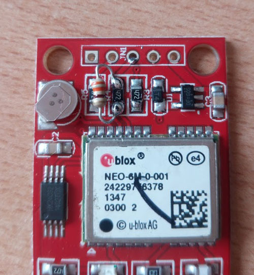
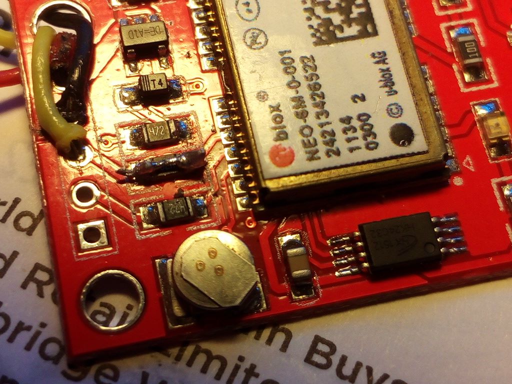
If you have one of the red NEO-6m boards or this might apply to other boards, theres a problem with the resistors on some of the boards stopping the flow of the nmea lines. If you dont get any output from D4, we suggest you add a 330ohm resistor across the middle resistor on the board - neo resistor , this is the prefered approach, however if you dont have one you solder a wire around this resistor or short it with solder, then check again. See this pic for details
Part Three - Check RF LORA
12.Now wire in the lora board and connect a blue LED with resistor as per the circuit diagram to the board.
13.Leave the FTDI adapter connected as per the previous step or connected to USB, as the board boots up it should say
RF LORA - attached
The blue TX light should start flashing when you now get a lock on the GPS.
14.Your wiring is now all correct and the system is up and running as it should be - now install into a case and go and test !
If you are only building one and wish to test then drive near a local ground station and see if you are on the web, alternatively if you purchase a Frequecy Scanner then you will be able to scan 868mhz and see your radio information being sent out.
|
|
|
|
 |
|
