This page will help you build a FLARM enabled version of AirWhere, we are adding a new radio board that sends a message out on the FLARM frequency so FLARM enabled traffic can see us, we can not see the FLARM traffic, they can just see us. If you wish to see FLARM traffic or learn more about FLARM please visit the www.flarm.com website and purchase one of their devices. This setup will still send and receive on the airwhere frequency so you will still see airwhere enabled devices and they will see you.
Required Knowledge
The install and setup procedure just requires basic computer knowledge, how to download files, install software and to be competent at soldering. Some fault finding and knowledge of serial communications is always useful but not necessary. If you have any issues building this device please pop on the AirWhere facebook group and ask, alternatively contact us.
Step One.
Firstly before you start you will need to register an ID for your unit.
| 1.1 | Proceed to the registration page and type in your email and choose a password and press sign up.
You will then receive an email asking you to confirm your email address, if you dont receive one, check spam to see if its there or any other issues - contact us.
|
| 1.2 | Once you have verified your email proceed to log in and then press add aircraft and add your details
Examine your FLARM board you purchase in the next step and there will be a code on top. Enter the first 2 digits into the manufacturer field and then next 4 into the ID field.
This will now be your flying number.
|
Step Two.
First we will describe the initial flarm setup which can be used via USB to a kobo and wifi/ble - we recommend this setup is built and configured first, perhaps on a breadboard to confirm all the hardware is ok and it is much easier to diagnose any issues. Once the flarm/airwhere system is seen to be working then proceed to install into your finished case/setup.
To
purchase the hardware you will be using please order the following items :- All these items and a kit are availble on our
shop site, please contact us if you cant find what your looking for. ( 1/3/2018 - items will be added to the shop site shortly )
To
integrate into a kobo the following items are required to build as per the later instructions, however if you are going to spec your own build, purchase whats necessary.
There are also various parts to fit the various different kobos - we do a full kit of parts to make your own, if this is too much for you we also supply a complete ready to go version.
Step Three.
Once the purchased hardware arrives you will need to install the windows / mac drivers to be able to ‘see’ the board and then install the AirWhere software onto it.
| 3.1 |
Load this page and then download the relevant driver for windows and install.
https://www.silabs.com/products/development-tools/software/usb-to-uart-bridge-vcp-drivers
|
| 3.2 |
Extract the zip file to a folder and then run the correct executable in the file.
If your on 32 bit windows, run the exe with 86 in it and if your on a 64 bit windows run the 64 version. Your version can be found in windows device manager.
|
| 3.3 |
Now you should be able to get a micro usb cable and plug your AirWhere board in..
Windows should say its found the hardware and that is now working.
|
| 3.4 |
Open windows device manager (control panel – device manager). Find ‘Ports’ you should see a new port there, perhaps com3 or com4 which is your new board.Take a note of this number you will need this in the next step.
|
Step Four.
Programming Files:
| 4.1 |
Create a new folder on your PC.
Name the folder but DO NOT allow any spaces between letters. |
| 4.2 |
You will need to download into this folder 4 files:
- ESPFlasherGUI.exe from =https://github.com/neoxharsh/ESP32-GUI-Flasher/tree/master/dist
This is the flasher program you will be using (Windows only, for the Mac see this page)
The next three files are available either on the AirWhere down loads page http://www.airwhere.co.uk/airware-downloads.php
or you may find them under files on the Airwhere-ESP32_Pilots Only page on facebook.
- Bootloader called bootloader.bin
- Partition called default.bin
- Application currently called AirWhereESP32.bin
This may change so check facebook for the live version or for the latest unstable version AirwhereESP32Dev.bin
Please make sure there are NO spaces in any of the file names and the directory it is in, this will create an issue.
|
4.3 |
Plug the ESP32 into a microUSB and into a USB port on your computer.
The OLED may say Heltic and then start counting packets it is transmitting. Ignore this and carry on.
| 4.4 |
Double click on the ESPFlasherGUI.exe file and link the Bootloader, Partition and Application files.
| 4.5 |
Select and check the COM port (you checked device manager for this number before)
For example COM11 (even though the correct port may appear in the box you MUST click on the drop down and reselect it or the download will fail).
| 4.6 |
Select the memory size 4MB.
| 4.7 |
Finally press FLASH and immediately after press the PRG on the board once.
The card will start to write the data, takes about 9s. You may find the programme terminates with a message that says it is rebooting and a flashing light on the ESP32 board. Ok this has probably worked. ( We have seen the buttons on the ESP32 board marked up incorrectly, so if you try one button and it fails with "cant find packet head" or similar, just try the other button, some need it held until the flashing process starts and then let go. )
| 4.8 |
Now check to see if you can see the AirWhere ESP32 board on your wifi settings.
|
Step Five.
So now you have a working ESP32 board with the AirWhere program.
| 5.1 |
Search for the new device in your wifi settings and connect to it..
You will be asked for default password 12345678. ( this password could have been changed when the unit was built so check with the builder.)
|
| 5.2 |
Now type 192.168.4.1 in your web browser.
If you are using an android phone please switch your data off, android will try look for airwhere on the internet and the connection will take a long time.
You will now see a page titled AirWhere ESP32. This is the configuration page.
|
| 5.3 |
Then use the Configure Pilot Info button to enter your details, the ID field will be disabled and will be filled in by the FLARM board later when its connected.
.
When you press ‘Submit’ the device will try to return to the home page but when the FLARM board is attached it will create a new access point with your new number, therefore will require to be searched for and connected to.
|
| 5.4 |
Reconnect this wifi device then refresh 192.168.4.1.
|
| 5.5 |
Click ‘Pilot Info’, input your pilot details, your Wifi SSID and Password..
This will allow you to upgrade the software via your Wifi connection.
|
| 5.6 |
When you’ve completed the settings press submit.
The unit will restart so go back to the home page again once its started.
|
| 5.7 |
Press ‘Configure Hardware’ and under ‘Radio board’ select ‘FLARM board’.
the other choices depend on what you are building and have attached.
|
| 5.8 |
Select in flight software select what software you will be using and which platform.
(as we want to connect to an android phone in this version).
|
| 5.9 |
Select which baud rate your gps uses, if its a standard gps they are mainly 9600 such as the PA6C shown on the circuit diagram later.
however the bluefly vario uses 57600 as standard, this will be your kobo connection speed aswell so make a not of this number.
|
| 5.10 |
In connection mode choose OTG/Serial Mode ( GPS attached to ESP32, this will be main mode that the flarm setup will be used, apart from wifi mode. Again press submit and reconnect to home page..
Sometimes this take a couple of mins, if it hangs, refresh your browser 192.168.4.1. You should now be back on the home page for your device. If the page times out, just refresh and it will appear again.
|
Step Six.
This step is optional but we recommend it as it will help diagnose any issues and will confirm the setup and hardware is operational before proceeding to install into a case.
| 6.1 |
Download putty https://www.chiark.greenend.org.uk/~sgtatham/putty/latest.html - this is an application that will let you see the output from airwhere and will help see if everything is working ok.
|
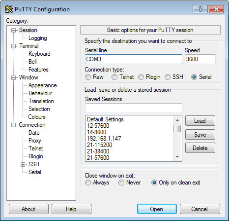
| 6.2 |
Install this and then run the application, on the first screen press the serial radio button and then add your com port as you found earlier and then type in a (baud rate ) speed, which you defined earlier in AirWhere ( 9600 or 57600 probably ).
|
| 6.3 |
Plug the ESP into a spare usb port on the computer.
if you stick with the same port everytime it will hopefully stay on the same com port, but check device manager anyway to make sure.
|
| 6.4 |
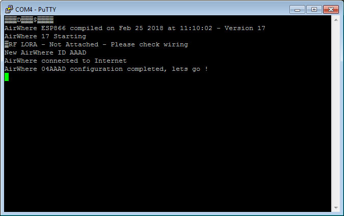
The next screen will probably come up blank - press reset on the esp8266 board and then text will start scrolling out in this screen showing you something similar to the following lines.
|
We would recommend checking this as you install the components and check the system.
Step Seven.
| 7.1 |
Follow the wiring diagram to setup the AirWhere FLARM board.
a breadboard can be used to temporarily check the system works ok, however soldering gives a better joint.
| ESP32 | FLARM board | Aerial | Power LED | GPS Lock LED | GPS | Kobo |
| IO2 | RESET | | | | | |
| IO4 | PPS | | | +ve | PPS | |
| IO17 ( TX2 ) | RXD | | | | | |
| IO16 ( RX2 ) | TXD | | | | | |
| 23 | | | | | TX | |
| 3V | VCC | | +ve | | +VE/VCC | +ve (TP2 - optional) |
| GND | GND | Outer | -ve | -ve | -ve | GND/-VE |
| ANT | Inner | | | | |
|
| 7.2 |
After the diagram has been followed, connect the board to usb and run putty as in the previous step, the flarm board should now be found and gps data appear on the application.
|
| 7.3 |
As the GPS gets its first lock, it can take a while from cold.
the text AIRWHERE TRANSMITTING LOCATION should appear on the screen amongst the gps statements, this shows your build is now working.
|
| 7.4 |
If your wifi and wifi password have been added to the config, the device should be seen on the AirWhere tracking page.
|
| 7.5 |
Update your FLARM board.
all boards require a freely available yearly update from FLARM, this is done automatically and navigating to "configure hardware" on the AirWhere configuration page will facilitate this. If your FLARM board is installed correctly the expiry date will be shown on this screen , please press update FLARM board and then update. Your board will reboot after this has finished, reconnect again to see the new expiry date. If the date is the same, try again, there may have been network issues. ( If it has failed the board will say not connected, dont worry this is normal, please try updating again )
|
At this point the unit can be connected to USB or switched to wifi mode and connected to a working kobo or android.
Information can be found on Step Seven of this
page on how to complete this. The only difference being speed ( baud rate ) you have configured before.
Notes : If your gps takes a 3-5V input then sometimes ( or if its not working ) attach the positive on the GPS to the 5V on the ESP32 board. This sometimes can help give it a bit more power for a better lock.
If your using a bluefly vario then the pps is in a different place than the above diagram, please check the
data sheet
Step Eight.
| 8.1 |
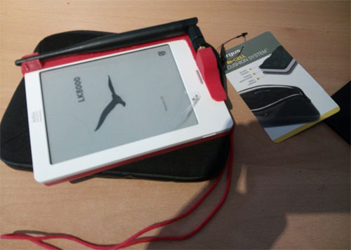
Follow the wiring diagram to setup a battery powered AirWhere FLARM setup to fit into a kobo case.
we have cases available for most Kobos, click on the image to enlarge
| ESP32 | FLARM board | Aerial | Power LED | GPS Lock LED | GPS | Kobo |
| IO2 | RESET | | | | | |
| IO4 | PPS | | | +ve | PPS | |
| IO17 ( TX2 ) | RXD | | | | | |
| IO16 ( RX2 ) | TXD | | | | | |
| 23 | | | | | TX | |
| IO1 ( TX0 ) | | | | | | RX |
| IO3 ( RX0 ) | | | | | | TX |
| 3V | VCC | | +ve | | +VE/VCC | +ve (TP2 - optional) |
| GND | GND | Outer | -ve | -ve | -ve | GND/-VE |
| ANT | Inner | | | | |
|
| 8.2 |
After connecting the serial port on the Kobo to TX of the AirWhere board, you can configure LK8000 or XCSoar.
|
| 8.3 |
Connecting a BlueFly GPS/Vario.
exchanging a standard gps with a BlueFly is detailed on the bluefly vario page, it requires small modification to the bluefly vario to support the flarm board.
|
| 8.4 |
For more info on how to install into a Kobo we have added some images and more details here |
Step Nine.
Now we proceed onto configuring the Kobo.
LK8000
| i |
Connect to the AirWhere home page by connecting to its wifi and going to 192.168.4.1..
|
| ii |
Click Configure Hardware. Then under ‘Flight Software’ choose ‘XCSoar - Kobo’ and click ‘Submit’. The board will restart..
|
| iii |
First you need to install the Kobo software - choose LK8000 or XCSoar and navigate to their respective websites and download what you like to use, there is a dual boot version available if you wish to run both on your kobo to try them both out.
|
| iv |
There are several websites regarding this procedure if you search the web for this, however please first update your kobo by wifi or by downloading the kobo desktop software off the kobo website, make sure your kobo is up to date first, without this procedure your kobo may crash. Once you have updated, plug the kobo into the USB on your pc and then it should create a new drive, navigate to ths drive and copy the flight software you have chosen to the directory called .kobo , once this has completed, unplug the kobo and it will restart and install the software for you.
|
| v |
Now take your OTG usb lead and plus it into the a usb battery supply, then into the kobo, the remaining plug into the AirWhere unit. the AirWhere screen should start once more and show some information.
|
| vi |
LK8000 now requires configuring to let it see the AirWhere unit. If you proceed to the menu system, bottom right menu, config, config, LK8000 setup, Device Setup. Now add these details in the first Device, device A.
Name : Generic
Port : /dev/ttymxc0
Ext. Sound : On
BaudRate : ( the value in your AirWhere config ) 8bit
|
| vii |
Press close.and then a line saying restarting comm ports will come on screen, then detected FLARM, this shows your system is working. When your kobo gets a GPS lock, the T: value on the airwhere board will start increasing, this shows your system is sending out your location.
|
| viii |
Press the middle of the bottom info bar and the flarm screens will come up, check the airwhere video sections for usage.
Hint - to see traffic on the main map, go to ‘config’ and on page 13 at the bottom ‘enable traffic’.
|
XCSoar
| i |
Connect to the AirWhere home page by connecting to its wifi and going to 192.168.4.1..
|
| ii |
Click Configure Hardware. Then under ‘Flight Software’ choose ‘XCSoar - Kobo’ and under ‘Connection mode’ click ‘Submit’. The board will restart..
|
| iii |
Load XCSoar.
|
| iv |
Double click on the plane icon at the bottom and bring up the menu. Click ‘Config’ and click.
|
| iv |
Edit Device A:-
Port : /dev/ttymxc0
Baud Rate : ( the value in your AirWhere config )
Driver : Generic.
|
| iv |
XCsoar should now be picking up data and a gpslock.
|
When AirWhere sees another user it will be shown as FLARM traffic in the XCsoar application.
That’s it, Airwhere is now configured!
Addendum.
If there are any problems during the install please check the following.
| i. |
Double check config settings - ie OTG Mode / GPS etc. |
| ii. |
FLARM board is updated. |
| ii. |
If there are some issues that stop the board working properly, please try updating to the development version before emailing in. Your issue may have been fixed already but not tested and released live. |
Have fun with the project!